


 English
  中文简体
中文简体 • The CNC Knife Grinding Machine adopts PLC program control, which is easy to operate, fast, stable,...
See DetailsHow Does a Circular Knife Grinding Machine Work?
Industry News-Content
- 1 Stage 1 -- Knife Mounting and Datum Setting
- 2 Stage 2 -- The Grinding Wheel: Abrasive Action and Material Removal
- 3 Stage 3 -- Knife Rotation During Grinding
- 4 Stage 4 -- The Feed Control System: Infeed and Traverse Axes
- 5 Stage 5 -- The Coolant System: Heat Management During Grinding
- 6 Stage 6 -- Wheel Dressing: Maintaining the Grinding Wheel's Cutting Condition
- 7 Stage 7 -- The Complete CNC Grinding Cycle From Start to Finish
- 8 CNC Control: How Programming Delivers Repeatable Results
- 9 Bevel Angle Setting: Geometry of the Grinding Process
- 10 Measuring Results: How Knife Quality Is Verified After Grinding
- 11 How the MYD Series Works in Practice: Key Design Features
- 12 Common Grinding Problems, Root Causes, and Corrective Actions
A Circular Knife Grinding Machine works by mounting a circular (rotary) slitter knife on a precision spindle, rotating it at a controlled low speed, and bringing a rotating abrasive grinding wheel into contact with the knife's cutting edge at a programmed angle, infeed depth, and traverse speed. The grinding wheel removes micro-layers of steel from the blade edge in a sequence of roughing, semi-finishing, and finishing passes until the cutting bevel is restored to the specified geometry, surface finish, and diameter. The entire process is governed by three interdependent systems -- the grinding wheel drive, the knife holding and rotation mechanism, and the CNC feed control -- working in coordinated sequence to produce a repeatable, geometrically accurate cutting edge.
The circular knife grinding machine is specifically designed for regrinding the circular (disc-shaped) slitter blades used in slitting and rewinding lines across the paper, film, foil, nonwoven, adhesive tape, textile, and flexible packaging converting industries. Unlike surface grinders or cylindrical grinders, it is purpose-built to hold, rotate, and grind circular knives with extreme concentricity -- because a circular knife that has been reground with even 0.01 mm of runout will produce uneven slit quality on a high-speed converting line. Understanding each stage of the working process in detail is the most practical way to specify, operate, and maintain these machines correctly.
Stage 1 -- Knife Mounting and Datum Setting
Every grinding cycle begins with mounting the circular knife on the machine spindle and establishing the grinding datum -- the reference position from which all programmed infeed movements are measured. These two steps must be performed correctly before any grinding begins, because errors here propagate through the entire grinding cycle and produce a knife that does not meet its dimensional specification regardless of how well the grinding passes themselves are executed.
Spindle and Arbor Systems
The circular knife is mounted on a precision-ground spindle arbor using one of several clamping arrangements depending on the knife bore diameter and the machine design:
- Collet chuck: A spring-steel collet closes concentrically on the knife bore when the drawbar is tightened, centering the knife on the spindle axis. Collet systems achieve runout values of less than 0.003 mm TIR (Total Indicator Reading) when the collet and bore are clean and undamaged -- essential for the concentricity of the ground knife.
- Hydraulic expansion arbor: A hydraulic fluid chamber expands an outer sleeve to grip the knife bore. Hydraulic arbors provide excellent centering repeatability and are preferred for production grinding of multiple identical knives where setup time must be minimized.
- Precision flanged arbor with clamping nut: The knife sits against a ground flange face and is clamped axially by a nut. This system is less sensitive to bore diameter variation and is used for knives with non-standard bore sizes or irregular bore conditions from previous wear.
Before mounting, both the spindle arbor surface and the knife bore must be cleaned of all chips, coolant residue, and surface contamination. A particle of swarf between the arbor and bore displaces the knife off-center by the full particle thickness -- a 0.05 mm chip produces 0.05 mm of runout, which is unacceptable for precision film or foil slitter knives where the tolerance is typically less than 0.005 mm TIR.
Datum Setting and Surface Probing
Once the knife is mounted, the machine establishes the grinding datum by probing the knife face with either a contact probe (a hardened stylus that touches the knife surface and registers the contact position) or a non-contact sensor (eddy current or laser). The probed position tells the CNC controller exactly where the knife face is located in the machine coordinate system, so that the programmed total infeed (the amount of steel to be removed) is applied from the actual knife surface rather than from an assumed nominal position.
This datum step is what prevents the most common error in manual grinding -- removing too much or too little material because the operator misjudges where the wheel first touches the knife. On CNC circular knife grinding machines, the datum probe resolves to 0.001 mm or better, ensuring the grinding cycle removes precisely the programmed amount of material regardless of variation in knife diameter from previous regrinds.
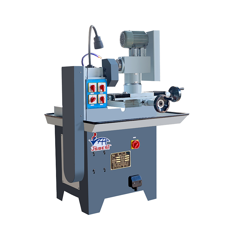
Stage 2 -- The Grinding Wheel: Abrasive Action and Material Removal
The grinding wheel is the primary cutting element of the machine. It is a bonded abrasive tool -- millions of abrasive grains held in a vitrified, resinoid, or metal bond matrix -- that rotates at high peripheral speed. Each exposed abrasive grain on the wheel face acts as a single-point cutting tool, shearing off a microscopic chip of knife steel at the point of contact with the knife edge. This is mechanically equivalent to conventional turning or milling, but at a scale of micrometers per grain rather than millimeters per tool pass.
Grinding Wheel Speed and Peripheral Velocity
Grinding wheel peripheral speed -- the speed of the wheel rim at the point of contact with the knife -- is the most critical operating parameter affecting both surface finish and wheel life. Standard aluminum oxide wheels for circular knife grinding operate at peripheral speeds of 25 to 35 m/s. CBN (Cubic Boron Nitride) superabrasive wheels operate at 35 to 60 m/s. Higher peripheral speed increases the number of abrasive grain-to-steel contacts per second, producing a finer surface finish and reducing chip load per grain -- which both improves finish and extends wheel life.
Peripheral speed is calculated as: V = pi x D x n / 60, where V is peripheral speed in m/s, D is wheel diameter in meters, and n is wheel RPM. A 200 mm diameter wheel operating at 2,865 RPM achieves a peripheral speed of approximately 30 m/s -- the center of the optimal range for aluminum oxide wheels on tool steel knife grinding (source: Norton Abrasives Grinding Application Guide, 2020).
Abrasive Grain Types for Circular Knife Grinding
| Abrasive Type | Hardness (Mohs / Knoop) | Best For | Limitations |
|---|---|---|---|
| Aluminum Oxide (Al2O3) | 9 Mohs / ~2,000 Knoop | HSS and D2 tool steel knives; general-purpose circular knife grinding | Wears faster on hardened carbide; moderate wheel life |
| Silicon Carbide (SiC) | 9.5 Mohs / ~2,500 Knoop | Harder steels; occasionally used for carbide-tipped knives at light stock removal | More brittle than Al2O3; less suitable for shock-loaded cuts |
| CBN (Cubic Boron Nitride) | ~4,700 Knoop | Hardened HSS (60+ HRC); high-production circular knife regrinding | Higher wheel cost; requires specific machine spindle power and rigidity |
| Diamond (Synthetic) | ~7,000 Knoop | Tungsten carbide circular knives for foil and film slitting | Reacts chemically with steel at high temperatures; not suitable for steel knives |
For the majority of circular knife grinding applications -- HSS and D2 steel slitter blades for paper, film, and nonwoven converting -- vitrified aluminum oxide wheels in grit sizes 46 to 80 for roughing and 100 to 220 for finishing are the standard specification. CBN wheels are justified for high-production facilities grinding large numbers of hardened HSS knives where longer wheel life and faster cycle times offset the higher wheel cost.
Wheel Face Geometry and Bevel Formation
The shape of the grinding wheel face -- whether flat, angled, or radiused -- directly determines the bevel geometry produced on the knife edge. A flat wheel face produces a flat bevel; a radiused or concave wheel face produces a hollow grind -- a slightly concave bevel that reduces the included angle at the cutting edge tip while maintaining steel backing behind the edge. Hollow grinds are preferred for film and foil slitter knives because the reduced tip angle gives a sharper cutting action with less drag on the slit edge.
The bevel angle itself -- the angle between the wheel face and the knife face at the contact point -- is set by tilting either the grinding head or the knife spindle to the required angular position before the grinding cycle begins. Common included bevel angles for circular slitter knives range from 30 degrees for film and foil applications to 55 degrees for paper and board, with the specific angle for each application determined by the knife steel grade, the substrate being slit, and the line speed.
Stage 3 -- Knife Rotation During Grinding
While the grinding wheel provides the cutting action, the circular knife itself must rotate slowly during grinding so that the wheel works progressively around the full 360 degrees of the knife circumference. This knife rotation is what makes a circular knife grinding machine fundamentally different from a flat knife sharpener or a standard surface grinder -- the rotating workpiece requires a dedicated rotation drive system and concentricity-maintaining spindle design that are central to the machine's design.
Knife Rotation Speed
The knife rotates at a slow, controlled speed during grinding -- typically 3 to 25 RPM depending on knife diameter, grinding wheel infeed depth, and the required surface finish. Slower rotation allows more grinding wheel contact time per unit of knife circumference, producing a finer finish. Faster rotation moves more of the knife through the wheel contact zone per unit of time, increasing material removal rate but reducing finish quality.
For a 200 mm diameter knife grinding at 10 RPM, the knife circumference travels at approximately 105 mm/s through the wheel contact zone. For a 450 mm knife at the same RPM, the circumference speed is 236 mm/s -- which means the wheel is effectively traversing faster relative to the knife surface, requiring either slower knife rotation or faster wheel peripheral speed to maintain equivalent surface finish. CNC circular knife grinding machines compensate for this automatically when the knife diameter is entered into the program, adjusting the rotation speed to maintain consistent surface speed at the wheel contact point across different knife sizes.
Spindle Runout: The Critical Concentricity Parameter
The spindle that drives the knife rotation must maintain the knife on a perfectly true circular path during grinding. Any runout (eccentricity) in the spindle bearing causes the knife to wobble as it rotates, which translates directly into diameter variation around the knife circumference after grinding. In a gang-slitter where multiple knives must match in diameter to within 0.01 mm, spindle runout is the primary limiting factor in achievable knife diameter consistency.
Quality circular knife grinding machines specify spindle runout of less than 0.002 mm TIR, achieved through precision angular contact bearings preloaded to eliminate clearance, ground spindle journals, and thermally stable spindle housing design. This specification is verified during machine acceptance testing with a high-resolution dial indicator or laser interferometer, and should be re-verified periodically as part of machine preventive maintenance because bearing wear gradually increases runout over time.
Stage 4 -- The Feed Control System: Infeed and Traverse Axes
The feed system is the mechanism that controls the position, speed, and depth of the grinding wheel relative to the knife face at every instant during the grinding cycle. It consists of two independent linear motion axes that together define all aspects of the material removal process.
The Infeed Axis (X-Axis)
The infeed axis moves the grinding wheel toward the knife face, bringing the abrasive surface into contact and advancing it by a programmed increment after each pass to remove successive layers of steel. The infeed resolution of a quality CNC circular knife grinding machine is 0.001 mm (1 micrometer) per step, allowing the grinding program to specify infeed increments as small as 0.001 mm for the finest finishing passes. Typical infeed values by grinding phase are:
- Roughing passes: 0.01 to 0.03 mm per pass -- removes the bulk of worn or damaged material quickly; surface finish is coarse but accuracy at this stage is not critical
- Semi-finishing passes: 0.005 to 0.01 mm per pass -- refines the bevel geometry established in roughing; surface roughness begins approaching the final specification
- Finishing pass: 0.001 to 0.003 mm per pass -- produces the final surface finish and geometry; surface roughness of Ra 0.2 to 0.8 micrometers is achievable in this phase
- Spark-out pass: Zero additional infeed -- the wheel traverses the knife face without advancing further, allowing residual grinding forces and elastic deflection to relax and producing a finer finish than the last infeed pass alone
The Traverse Axis (Z-Axis)
The traverse axis moves the grinding wheel across the width of the knife bevel face, ensuring uniform stock removal across the full bevel width in each pass. Traverse speed is a critical parameter because it determines both the material removal rate and the surface finish quality:
- Fast traverse (100 to 400 mm/min): Used during roughing passes for high material removal rate; leaves visible traverse marks on the ground surface
- Slow traverse (20 to 80 mm/min): Used during finishing passes; reduces traverse marks and improves surface uniformity across the bevel width
- Spark-out traverse: Typically at the finishing traverse speed with zero infeed; produces the finest achievable surface finish for the wheel grit and bond specification
Both axes are servo-driven on CNC machines, with position feedback from linear encoders or ballscrew-mounted rotary encoders. The CNC controller reads the axis positions in real time and compares them to the programmed trajectory, correcting any deviation within milliseconds. This closed-loop position control is what enables the 0.001 mm infeed resolution and the traverse speed consistency that produce repeatable grinding results across hundreds of knife cycles.
Stage 5 -- The Coolant System: Heat Management During Grinding
Grinding generates intense localized heat at the wheel-to-knife contact zone through friction and plastic deformation of the metal chip. Without active cooling, the knife edge temperature can rise to 300 to 800 degrees Celsius within seconds, well above the tempering temperature of most tool steels used for circular slitter knives (typically 150 to 200 degrees C for D2 steel at 60 to 62 HRC). Exceeding the tempering temperature reduces the hardness of a band of steel near the cutting edge -- visible as a blue or brown heat tint on the ground surface -- creating a soft zone that dulls rapidly in service.
Four Functions of the Grinding Coolant
- Heat removal: Flood coolant directed at the grinding contact zone absorbs thermal energy from the wheel-knife interface and carries it away from the knife before it can conduct into the steel bulk and raise the subsurface temperature above the tempering threshold.
- Chip flushing: Coolant flow removes metal swarf and abrasive grain fragments from the grinding zone. Without flushing, chips accumulate between the wheel face and the knife surface, causing them to be re-cut -- which generates additional heat and degrades surface finish.
- Wheel cleaning (anti-loading): Continuous coolant flow prevents metal chips from embedding in the pores of the grinding wheel face -- a condition called loading -- which reduces cutting efficiency and generates additional heat from friction between the clogged wheel and the knife surface.
- Corrosion prevention: Water-based coolants include rust inhibitor packages that protect both the freshly ground knife surface and the machine's steel components from rust formation between operating sessions.
Coolant Specification and Maintenance
Grinding coolant for circular knife grinding is typically a water-soluble oil or synthetic coolant diluted to 3 to 8% concentration in clean water. The concentration must be maintained within this range: too dilute reduces lubricity and rust protection; too concentrated increases foaming, reduces heat transfer efficiency, and accelerates biological growth in the sump. Coolant pH should be maintained between 8.5 and 9.5 -- the alkaline range that inhibits bacterial growth and provides the best rust protection for steel knife surfaces (source: IMTS Metalworking Fluid Management Guidelines, 2021).
Coolant flow rate at the grinding zone should be sufficient to fully flood the contact arc -- typically 10 to 20 liters per minute for circular knife grinding applications. Inadequate flow is the most common cause of thermal damage (burning) to knife edges during grinding, even when the correct coolant concentration is maintained. The coolant nozzle should be positioned as close as possible to the wheel-knife contact point, directed to intercept the boundary layer of air that the spinning wheel carries with it -- which would otherwise deflect the coolant stream away from the critical contact zone.
Stage 6 -- Wheel Dressing: Maintaining the Grinding Wheel's Cutting Condition
As the grinding wheel cuts, two things happen progressively: the abrasive grains wear and become rounded (losing their cutting sharpness), and metal chips become embedded in the wheel face pores (loading). Both conditions reduce cutting efficiency, increase grinding forces, increase heat generation, and degrade surface finish. Wheel dressing is the process of resharpening and re-truing the wheel face to restore its cutting condition.
How Dressing Works
A diamond dressing tool -- either a single-point diamond, a diamond impregnated roller, or a multi-point diamond cluster -- is traversed across the wheel face at a controlled feed rate and depth. The diamond tool fractures the outermost layer of abrasive grain and bond matrix, removing worn and loaded material and exposing fresh, sharp abrasive grain beneath. The traverse rate of the diamond across the wheel (the dress lead) controls the resulting wheel face topography: a slow traverse creates a smoother wheel face that produces a finer surface finish; a fast traverse creates a more open, aggressive wheel face that removes material faster but leaves a coarser finish.
On CNC circular knife grinding machines, wheel dressing is programmed as a sub-routine within the grinding cycle and executed automatically at defined intervals -- either after a set number of knife passes, after a set amount of total grinding time, or when a spindle load or acoustic emission sensor detects that the wheel condition has deteriorated below a threshold. Automatic dressing eliminates the operator judgment error that is the most common cause of inconsistent surface finish in manual grinding operations, and ensures that every knife in a production batch is ground with a wheel in equivalent cutting condition.
Wheel Wear Compensation
Each dressing cycle removes a small amount of the grinding wheel diameter. As the wheel diameter decreases, its peripheral speed decreases for the same RPM (since V = pi x D x n / 60), and its position relative to the knife face changes. Without compensation, a shrinking wheel would produce progressively undersize knife bevels and operate at progressively lower peripheral speed.
CNC circular knife grinding machines compensate for wheel wear automatically by tracking the total depth removed during dressing cycles and offsetting the infeed axis position to maintain the correct wheel-to-knife relationship. This wheel wear compensation is transparent to the operator -- the machine continues to deliver the correct knife geometry regardless of the current wheel diameter, until the wheel reaches its minimum usable diameter and must be replaced. On the MYD Series Circular Knife Grinding Machine, this compensation operates in real time with no operator input required between wheel changes.
Stage 7 -- The Complete CNC Grinding Cycle From Start to Finish
With the individual system components understood, the complete grinding cycle can be described as an integrated sequence. On a CNC circular knife grinding machine, this sequence is stored as a program in the machine controller and executed automatically after the operator loads the knife and initiates the cycle.
- Program recall and parameter entry: The operator recalls the stored grinding program for the knife type (or creates a new program by entering the knife diameter, bevel angle, total stock removal, pass schedule, and wheel specification). The machine sets the spindle tilt to the programmed bevel angle and moves the wheel to the start position.
- Knife mounting and probing: The operator mounts the knife on the arbor, cleans the mating surfaces, and confirms secure clamping. The machine probes the knife face to establish the datum position and enters it into the CNC coordinate system.
- Coolant system activation: The coolant pump starts and flow is verified at the grinding nozzle before the wheel advances to the knife surface. Never allow the wheel to contact the knife without coolant flowing.
- Wheel approach and air-cut: The grinding wheel advances toward the knife face at rapid traverse speed until it reaches the approach position, then slows to the grinding feed rate for the first contact. The machine detects first contact through spindle load monitoring or acoustic emission sensing, confirming the datum position and beginning the first roughing pass infeed increment.
- Roughing passes: The CNC executes the programmed number of roughing passes at the specified infeed depth per pass and traverse speed. The knife rotates continuously throughout. The machine monitors spindle load during roughing and can automatically reduce infeed depth if load exceeds the programmed maximum, protecting both the knife and the wheel from overload.
- Automatic dressing (if scheduled): After the programmed number of roughing passes, the wheel retracts to the dressing position and the diamond dresser traverses the wheel face. The machine registers the dressing depth and applies the corresponding wheel wear compensation offset before returning to the grinding position.
- Semi-finishing passes: Infeed is reduced to the semi-finishing specification and traverse speed decreases. The knife continues rotating. These passes refine the bevel geometry and begin producing the surface finish required for the final phase.
- Finishing and spark-out passes: Infeed reduces to the minimum finishing increment or zero (spark-out). Traverse speed is at its minimum. The remaining elastic deflection in the grinding system is released during spark-out, and the knife surface achieves the programmed Ra finish specification.
- Wheel retraction and diameter measurement: The grinding wheel retracts to the clearance position. The machine measures the knife diameter using an integrated contact probe or the operator measures it with an external micrometer. The measured diameter is compared to the target and tolerance band. If within tolerance, the cycle is complete. If outside, additional corrective passes are executed automatically (on fully automated systems) or the operator initiates a correction pass (on semi-automated systems).
- Coolant stop and knife removal: After the final measurement confirms the knife is within tolerance, coolant flow stops, the knife spindle decelerates to a stop, and the operator removes the knife, cleans it, and transfers it to the finished parts rack.
A complete cycle for a standard circular slitter knife takes 3 to 10 minutes on a CNC machine, depending on the amount of stock removal required, the knife diameter, and the finish specification. This compares to 10 to 25 minutes for an equivalent manual grinding operation, with the additional advantage of consistent quality regardless of operator skill level or accumulated fatigue.
CNC Control: How Programming Delivers Repeatable Results
The transition from manual to CNC circular knife grinding is the single most impactful change in precision and productivity available to a converting facility's tool room. Manual grinding requires a skilled operator to set depth of cut, traverse speed, and bevel angle for every knife, and the result varies between operators and between shifts. CNC control replaces all these manual adjustments with stored programs that produce identical results for every knife run on every shift.
What a CNC Grinding Program Controls
A complete CNC grinding program for a circular knife specifies:
- Bevel angle (degrees from the knife face, typically 15 to 28 degrees per side for a 30 to 55 degree included angle)
- Total stock removal (mm) -- the total infeed from datum to finished dimension
- Number of roughing passes and infeed depth per pass (mm)
- Number of semi-finishing passes and infeed depth per pass (mm)
- Number of finishing passes and infeed depth per pass (mm)
- Number of spark-out passes
- Traverse speed for each grinding phase (mm/min)
- Knife rotation speed (RPM) for each grinding phase
- Wheel peripheral speed (m/s) for each grinding phase
- Dressing frequency (after every N passes, or after every N knives)
- Dressing depth and traverse rate
- Target knife diameter and tolerance (mm)
- Coolant on/off sequencing
A mid-range CNC circular knife grinding machine stores 50 to 200 complete knife programs, allowing a tool room serving multiple converting lines with different knife types to switch between programs in under 2 minutes -- a dramatic reduction from the 15 to 30 minutes required to manually set up a manual grinder for a different knife type. This program storage capability is particularly valuable in facilities that grind knives for paper, film, and foil lines, each requiring different bevel angles and finish specifications.
Operator Interface and Quality Data Recording
Modern CNC circular knife grinding machines provide a touchscreen operator interface that guides the operator through knife loading, program selection, and cycle initiation with minimal training required. Quality data -- measured knife diameter, grinding cycle time, number of passes executed, and any alarms or deviations -- is recorded automatically for each knife and can be exported to a quality management system for traceability and process analysis. This data record supports statistical process control (SPC) analysis of knife grinding consistency, allowing tool room supervisors to identify trends such as wheel wear patterns, systematic bevel angle drift, or increasing cycle times that indicate the need for machine calibration or wheel replacement.
Bevel Angle Setting: Geometry of the Grinding Process
The bevel angle of the reground knife determines its cutting performance on the slitting line. Too acute an angle produces an extremely sharp edge that dulls quickly and chips under the cutting loads of hard or thick substrates. Too obtuse an angle produces a durable but blunt edge that drags on the slit material and produces ragged edges. The correct bevel angle is a compromise determined by the knife steel grade, the substrate type and thickness, and the line speed.
| Substrate | Typical Included Bevel Angle | Knife Steel | Finish Required |
|---|---|---|---|
| Tissue and soft paper | 30 -- 40 degrees | HSS or D2 tool steel | Ra 0.4 -- 0.8 um |
| Kraft paper and board | 45 -- 55 degrees | D2 or CPM tool steel | Ra 0.4 -- 1.0 um |
| BOPP and PET film | 30 -- 45 degrees | HSS or carbide-tipped | Ra 0.2 -- 0.4 um |
| Aluminum foil | 30 -- 40 degrees | Tungsten carbide | Ra 0.2 -- 0.4 um |
| Pressure-sensitive adhesive tape | 45 -- 55 degrees | D2 / CPM tool steel | Ra 0.4 -- 0.8 um |
| Nonwoven fabric | 35 -- 50 degrees | HSS | Ra 0.4 -- 0.8 um |
| Battery electrode foil (copper / aluminum) | 25 -- 35 degrees | Tungsten carbide | Ra 0.1 -- 0.2 um |
The bevel angle is set on the machine by adjusting the angular relationship between the grinding wheel face and the knife face. On machines with a tilting spindle head, the spindle tilts to the programmed angle relative to the wheel face. On machines with a tilting wheel head, the wheel head tilts relative to the horizontal knife spindle. Either configuration achieves the same geometric result -- the wheel contacts the knife face at the programmed bevel angle -- but the tilting spindle design is generally preferred for its better access to the knife for measurement and inspection during the cycle.
Measuring Results: How Knife Quality Is Verified After Grinding
Grinding a knife to the correct geometry is only half the task -- verifying that the result meets the specification is equally important, particularly for gang-slitter applications where diameter consistency across a set of knives directly determines slit quality on the converting line.
Diameter Measurement
The knife diameter is measured at the blade rim using a micrometer, a digital caliper, or an integrated machine probe. For gang-slitter knife sets, all knives in the set must be ground to the same diameter within the specified tolerance -- typically +/- 0.005 to 0.01 mm for precision film and foil applications and +/- 0.02 to 0.05 mm for standard paper converting. Knives outside this tolerance range produce uneven slit widths and differential wear between adjacent knives on the slitter arbor.
Bevel Angle Verification
Bevel angle is verified using an optical profile projector, a laser angle measurement system, or a precision bevel protractor applied to the ground face. Angle tolerance for most applications is +/- 0.5 degrees from the specified included angle. Tighter tolerances of +/- 0.25 degrees are required for battery electrode foil slitting and pharmaceutical packaging film applications where edge geometry consistency is a validated process parameter.
Surface Finish Measurement
Surface finish of the ground bevel is measured with a contact profilometer (stylus instrument) that traverses the ground surface and reports the Ra (arithmetic mean roughness) value. The finished Ra value confirms that the correct wheel grit, traverse speed, and spark-out cycle have been applied. A Ra value higher than specified indicates insufficient finishing passes, contaminated coolant, a loaded wheel face, or excessive traverse speed in the finishing phase.
Edge Integrity -- Visual and Tactile Inspection
Beyond dimensional measurements, the ground knife edge must be inspected for:
- Thermal damage (burn marks): Blue or brown discoloration on the ground bevel indicating that the steel exceeded its tempering temperature during grinding -- caused by insufficient coolant, excessive infeed depth, or grinding without dressing a loaded wheel. Burned edges are soft and must be reground until all discoloration is removed.
- Chipping or micro-fracture: Visible chips on the cutting edge tip, caused by impact damage before grinding, by grinding brittle carbide knives with excessive infeed, or by thermal shock from intermittent coolant supply. Chipped edges require additional stock removal until the damage zone is fully ground away.
- Burr on the edge tip: A thin fin of metal left on the edge by the grinding process, particularly at the transition between the bevel and the flat face of the knife. Burrs are removed by a brief honing pass with a fine-grit stone or a deburring file applied to the flat face while holding the knife flat on a reference surface.
How the MYD Series Works in Practice: Key Design Features
The Circular Knife Grinding Machine in the MYD Series implements all of the working principles described above in a purpose-built design optimized for the circular slitter knife regrinding requirements of modern converting facilities. Several design features of this series are directly relevant to understanding how the machine delivers its performance specification:
Precision Spindle Assembly
The MYD Series uses preloaded angular contact bearings in a thermally compensated spindle housing, achieving spindle runout specification of less than 0.002 mm TIR. The spindle is driven by a variable-speed servo motor with closed-loop speed control, maintaining the programmed knife rotation speed within +/- 1 RPM regardless of grinding load variations during the cycle.
CNC Servo-Driven Feed Axes
Both the infeed and traverse axes use precision ballscrews driven by servo motors with linear encoder feedback, delivering the 0.001 mm positional resolution and the position repeatability of less than 0.002 mm that are required for consistent knife diameter results across production batches. The axes are protected by sealed linear guideways that maintain their precision despite the coolant and swarf exposure inherent in grinding operations.
Automatic Wheel Dressing with Compensation
The integrated diamond wheel dresser is servo-controlled and programmed as part of the grinding cycle, executing at the intervals specified in each knife program and automatically applying the wear compensation offset after each dressing cycle. This ensures that the first knife and the hundredth knife in a production batch receive identical grinding treatment, with consistent wheel cutting condition throughout.
Program Library and Data Recording
The machine controller stores up to 100 knife programs, accessible through a touchscreen interface with program parameter verification prompts that reduce operator errors during program selection. Grinding cycle data -- diameter measurement, cycle time, pass count, and any fault codes -- is automatically recorded to an internal log that can be exported via USB or network connection for quality management system integration. This data record supports the ISO 9001 process documentation requirements that most major converting facility operators now require from their tool room operations.
Common Grinding Problems, Root Causes, and Corrective Actions
Understanding how the machine works also means understanding what goes wrong when the output does not meet specification, and how to identify and correct the root cause:
| Problem | Root Cause | Corrective Action |
|---|---|---|
| Thermal burn marks on bevel | Insufficient coolant flow; excessive infeed depth; loaded wheel face | Check coolant flow rate and nozzle position; reduce infeed depth; dress wheel; regrind knife until burn zone is removed |
| Poor surface finish (Ra too high) | Traverse speed too fast in finishing phase; insufficient spark-out passes; worn or loaded wheel | Reduce finishing traverse speed; add spark-out passes; dress wheel with fine lead; verify wheel grit specification |
| Diameter variation around circumference | Spindle runout exceeding specification; dirty or damaged arbor mating surfaces; knife bore out of tolerance | Check and clean arbor and bore; measure spindle runout with indicator; service spindle bearings if runout exceeds 0.005 mm |
| Inconsistent diameter between knives in a batch | Datum probe error; inconsistent knife mounting; bevel angle drift between cycles | Verify probe calibration; standardize mounting procedure; check bevel angle setting and tighten any loose pivot locking hardware |
| Edge chipping after grinding | Excessive infeed depth on brittle carbide knives; thermal shock from intermittent coolant; pre-existing subsurface cracks | Reduce infeed depth to 0.005 mm per pass for carbide; verify continuous coolant flow; inspect knives for cracks before grinding |
| Bevel angle outside tolerance | Spindle tilt loose or drifted; bevel angle entry error in program; thermal expansion of spindle housing during extended production run | Verify and re-set bevel angle; check and tighten spindle tilt locking mechanism; allow warm-up period before critical grinding |
| Increasing cycle time per knife | Wheel loading (reduced cutting efficiency); dressing frequency too low; coolant contamination reducing lubricity | Increase dressing frequency in program; check coolant concentration and pH; replace coolant if contaminated |
Related products
-
-

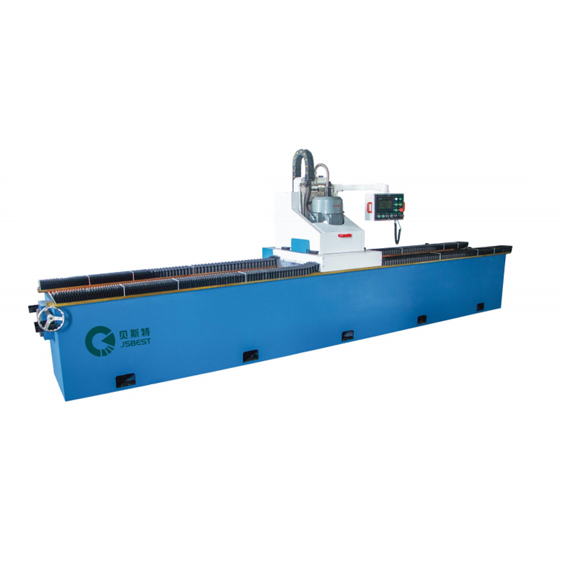
• The whole machine adopts a high-strength gantry-type welding structure, with a solid and compact o...
See Details -
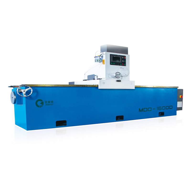
• The grinder adopts a gantry-type bed, high-quality steel plate welding, high-temperature tempering...
See Details -
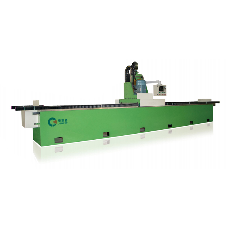
• A high-strength welded steel structure is adopted to eliminate the internal stress of the machine ...
See Details -
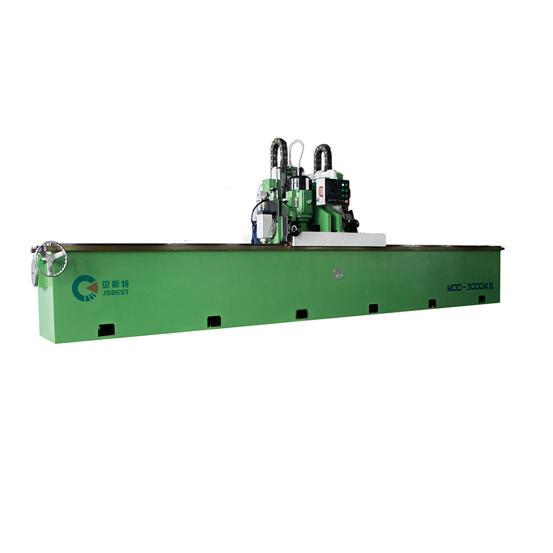
Double-Head Knife Grinding Machine is an efficient grinding equipment that combines rough grinding a...
See Details -
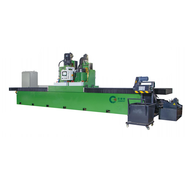
Heavy-Duty Surface Milling And Grinding Machine is an efficient processing equipment that integrates...
See Details -
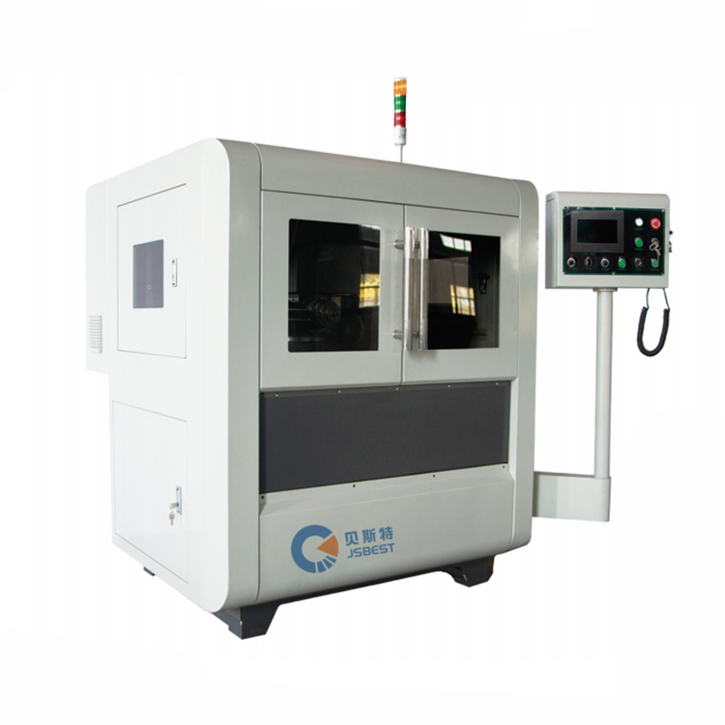
• This round knife grinder adopts a PLC program to control the automatic feeding part, which is easy...
See Details -
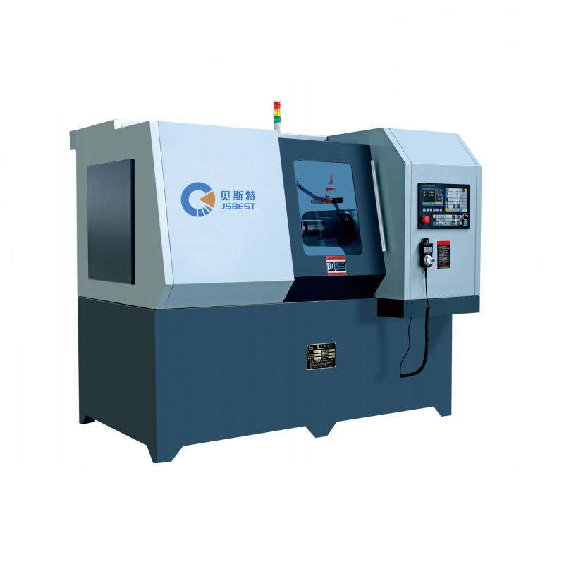
CNC Circular Knife Grinding Machine structural features:• High grinding accuracy, spindle and knife ...
See Details

- PRODUCT
- MDD Series Straight Knife Grinding Machine
- MYD Series Circular Knife Grinding Machine
- MCD Series Rewinding Knife Grinding Machine
- QUICK LINKS
- About Us
- Manufacturing
- Industry Solutions
- Downloads
- Contact
- CONTACT US
-
-
 No.99, Huanghai South Road, Tangyang Town, Dongtai City, Jiangsu Province, China
 -
 0086-13818631306
 -
 +86-515-85652988
 -

-

