


 English
  中文简体
中文简体 • The CNC Knife Grinding Machine adopts PLC program control, which is easy to operate, fast, stable,...
See DetailsHow to maintain a Straight Knife Grinding Machine?
Industry News-Content
- 1 Daily Maintenance: Cleaning, Inspection, and Lubrication
- 2 Weekly Maintenance: Guideways, Coolant, and Mechanical Checks
- 3 Monthly Maintenance: Drive Systems, Electrical Components, and Accuracy Checks
- 4 Quarterly Maintenance: Deep System Overhaul Tasks
- 5 Annual Maintenance: Full Precision Overhaul
- 6 Grinding Wheel Management: A Continuous Maintenance Responsibility
- 7 Maintenance Schedule Summary
- 8 Common Maintenance Problems, Causes, and Corrective Actions
- 9 Safety Requirements During Maintenance Operations
Maintaining a straight knife grinding machine correctly requires a structured program of daily cleaning, lubrication, and inspection combined with scheduled periodic overhauls of the grinding spindle, linear guideways, coolant system, electrical components, and fixturing system. Machines that receive consistent, properly executed maintenance deliver accurate, repeatable grinding results across long service lives — often exceeding 15 to 20 years — while machines that are neglected deteriorate rapidly in both precision and reliability, producing poor blade quality and generating costly unplanned downtime.
A straight knife grinding machine is a precision instrument. Its ability to restore a blade to geometric accuracy within tolerances of 0.01 mm or better depends entirely on the mechanical integrity of its guideways, spindle bearings, fixturing, and drive systems being maintained at or near their original specification. The maintenance program described in this article covers all major subsystems, organized by frequency — daily, weekly, monthly, quarterly, and annual — to allow production and maintenance teams to implement a complete and practical schedule.
Daily Maintenance: Cleaning, Inspection, and Lubrication
Daily maintenance tasks take 15 to 30 minutes at the start or end of each production shift and are the foundation of the entire maintenance program. Swarf accumulation, coolant contamination, and lubrication depletion are the three most common causes of accelerated wear in straight knife grinding machines, and all three can be effectively controlled through consistent daily attention.
End-of-Shift Cleaning
At the end of every production shift, the machine must be thoroughly cleaned before shutdown. Grinding swarf — fine metal particles and abrasive grains suspended in coolant — settles on every exposed surface during operation and, if left in place, becomes abrasive contamination that accelerates wear on guideways, ball screws, and seals. The following cleaning sequence is recommended:
- Switch off the grinding spindle and allow the coolant pump to continue running for 2 to 3 minutes to flush residual swarf from the grinding zone into the coolant tank.
- Use a low-pressure air blow-down (maximum 2 bar at the nozzle) or soft brush to remove swarf deposits from the machine table, workbench surface, magnetic chuck, and the grinding head housing. Never use high-pressure air directed at bearing housings or electrical enclosures — this forces contamination past seals rather than removing it.
- Wipe the guideway surfaces with a clean lint-free cloth dampened with machine oil to remove residual coolant and fine swarf particles that remain after blow-down.
- Clean the coolant tray and drain channels of accumulated swarf sludge. Blocked drain channels allow coolant to pool on the machine bed, accelerating corrosion of unprotected steel surfaces.
- Wipe down the exterior panels, control cabinet surfaces, and operator controls with a damp cloth.
Daily Lubrication Check
Most straight knife grinding machines use a centralized automatic lubrication system that delivers metered quantities of way oil to the linear guideways and ball screws at programmed intervals during machine operation. Each day before startup, verify the following:
- Check the centralized lubrication reservoir level and top up with the manufacturer-specified way oil grade (typically ISO VG 32 or ISO VG 68) if the level is below the minimum mark. A typical machine consumes 50 to 200 ml of way oil per 8-hour shift depending on the frequency of axis traversal.
- Verify that the lubrication pump cycles correctly during the machine warm-up sequence — most systems deliver an initial lubrication pulse at startup and then continue at timed intervals. Absence of lubrication pump cycling is a fault that must be investigated before production begins.
- Check for visible oil film on the exposed guideway surfaces after the startup lubrication pulse. Dry guideways after startup lubrication delivery indicate a blocked distribution line or failed pump output to that circuit.
- Inspect the grinding spindle for any signs of oil leakage from the bearing housing seals that would indicate seal deterioration.
Daily Visual Inspection
A brief visual inspection before each production shift catches developing problems before they become failures. Check the following each day:
- Grinding wheel condition — inspect for visible cracks, chips, or uneven wear. A cracked grinding wheel is a serious safety hazard and must be replaced immediately. Never operate the machine with a damaged wheel.
- Coolant level in the tank — operate with coolant below the minimum level causes the pump to draw air, reducing cooling effectiveness and potentially damaging the pump.
- Coolant delivery nozzle position — verify the nozzle is correctly aimed at the wheel-blade contact zone and has not been displaced by a blade loading operation.
- Magnetic chuck function — activate the chuck and verify the holding force indicator (if fitted) confirms correct magnetic strength before loading any blade.
- Drive belts (if the spindle uses belt drive) — check for unusual noise during spindle startup that might indicate belt wear or incorrect tension.
Weekly Maintenance: Guideways, Coolant, and Mechanical Checks
Weekly maintenance tasks take 1 to 2 hours and address components that accumulate wear or contamination over the course of a production week. These tasks should be scheduled for a consistent time — typically the beginning or end of the week — to ensure they are not displaced by production pressure.
Guideway Deep Cleaning and Inspection
Move the grinding head or workpiece table to each end of its travel range to expose the full length of the guideways. Using a clean cloth soaked in way oil, wipe the full length of each guideway surface to remove accumulated contamination that daily cleaning may not have fully addressed. Inspect the guideway surfaces under good lighting for scoring marks, pitting, or rust spots that indicate lubrication failure or contaminated coolant reaching the guideways past the wipers. Light surface rust can be removed with a fine oilstone and way oil; scoring or pitting deeper than 0.05 mm requires professional guideway rescraping or replacement.
Check the guideway wiper seals — the felt or polyurethane wiper strips fitted to the carriage ends that prevent swarf from entering the guideway contact area. Replace wipers that are worn, compressed, or contaminated with hardened swarf, as damaged wipers are the most common entry point for abrasive contamination into the guideways.
Coolant System Maintenance
The coolant system requires weekly attention to prevent bacterial growth, concentration drift, and swarf accumulation in the tank that degrade coolant performance and create hygiene and odor problems.
- Check coolant concentration with a refractometer. Water-soluble synthetic coolants should be maintained at the manufacturer-specified concentration — typically 4 to 8% for general steel grinding. Concentration below the minimum reduces both cooling performance and corrosion inhibition; above the maximum causes foaming and skin irritation risk.
- Remove accumulated swarf sludge from the bottom of the coolant tank using a scraper or suction pump. Heavy swarf accumulation reduces effective tank volume, raises coolant temperature, and provides nutrients for bacterial growth that causes rancid odor and coolant degradation.
- Check the coolant filter — clean or replace the filter element if flow through the filter is restricted. A clogged filter reduces coolant delivery to the grinding zone and may cause the pump to overheat.
- Inspect the coolant delivery nozzle for blockage by swarf particles. Flush with clean water if flow is reduced or uneven.
- Check coolant pH — most water-soluble grinding coolants should be maintained between pH 8.5 and pH 9.5. pH below 8.0 indicates bacterial contamination or excessive acid contamination from the grinding process and requires coolant replacement.
Wheel Dressing Tool Inspection
The diamond dressing tool (single-point diamond, diamond roll, or diamond dressing block) should be inspected weekly for wear. A worn dressing diamond produces a poorly conditioned wheel surface that results in chatter marks on the blade and inconsistent stock removal. Single-point dressing diamonds should be rotated by approximately 90° every 2 to 4 weeks to present a fresh facet to the wheel, extending the total usable life before replacement. Replace the dressing tool when it no longer produces a sharp, clean wheel surface after dressing, evidenced by poor surface finish on the blade immediately after dressing.
Monthly Maintenance: Drive Systems, Electrical Components, and Accuracy Checks
Monthly maintenance addresses the mechanical drive systems and precision accuracy of the machine — items that do not require daily or weekly attention but whose condition directly affects the quality of grinding results and the reliability of the machine over time.
Ball Screw and Lead Screw Inspection
The ball screws or lead screws that drive the traverse axis and the cross-feed (depth of cut) axis are among the most precision-critical components in the machine. Monthly, perform the following checks:
- Listen for unusual noise (grinding, scraping, or irregular clicking) during axis traversal, which may indicate inadequate lubrication or the beginning of ball track wear in the screw nut assembly.
- Check for excessive axial backlash in the cross-feed screw by moving the grinding head toward and away from the blade and measuring the lost motion with a dial indicator. Backlash exceeding 0.02 mm in the cross-feed axis directly translates to depth-of-cut inaccuracy and requires ball nut preload adjustment or ball screw replacement.
- Verify that the lubrication distribution lines serving the ball screw nuts are clear and delivering oil. Dry ball screws wear rapidly — a fully loaded ball screw operating without lubrication can deteriorate from new to replacement condition in as little as 200 operating hours.
Drive Belt Tension and Condition
On machines that use V-belts or poly-V belts to transmit power from the motor to the grinding spindle, check belt tension and condition monthly. Correct belt tension is specified by the machine manufacturer — typically measured as the force required to deflect the belt by 10 mm at the midpoint of the longest span. Under-tensioned belts slip under load, causing vibration and poor surface finish; over-tensioned belts overload the spindle bearings, accelerating bearing wear. Replace belts that show cracking, fraying, glazing, or visible cord separation.
Electrical System Inspection
With the machine isolated from power (following full lockout/tagout procedure), perform a monthly electrical inspection:
- Open the control cabinet and blow out accumulated dust with dry compressed air at low pressure. Dust accumulation on variable frequency drives (VFDs), contactors, and heat sinks raises operating temperatures and reduces component lifespan.
- Check all terminal connections for looseness caused by thermal cycling. Loose power terminals are a leading cause of control faults and represent a fire risk. Retighten any loose terminals to the specified torque.
- Inspect cable runs inside the machine for chafing, kinking, or coolant contamination. Damaged cable insulation must be repaired or replaced before the machine is returned to service.
- Test all limit switches and safety interlock functions to confirm correct operation. Safety interlocks — including wheel guard closure sensors and emergency stop buttons — must function correctly at all times.
Geometric Accuracy Verification
Monthly geometric checks verify that the machine is still grinding within its specified accuracy limits. Use a precision dial indicator mounted on the grinding head to check the following:
- Workbench flatness: Traverse the dial indicator across the workbench surface in both longitudinal and transverse directions. Flatness deviation should not exceed 0.015 mm per meter of length for precision knife grinding applications.
- Grinding wheel spindle runout: Mount the dial indicator against the wheel flange or spindle taper and rotate the spindle by hand. Radial runout should not exceed 0.005 mm; axial runout should not exceed 0.003 mm. Runout above these values produces waviness on the ground blade surface.
- Traverse axis straightness: Move the grinding head through its full traverse range while the indicator reads against a precision straight edge placed on the workbench. Deviation from straight should not exceed 0.01 mm over the full traverse length.
Quarterly Maintenance: Deep System Overhaul Tasks
Quarterly maintenance tasks address subsystems that require more extensive attention than monthly checks provide, but do not need annual-frequency overhaul. These tasks typically require 4 to 8 hours and may require specialist maintenance skills or tooling.
Full Coolant System Replacement
Even with weekly concentration and pH monitoring, coolant should be completely replaced every 3 months in single-shift operations, or every 6 to 8 weeks in multi-shift operations. Old coolant accumulates dissolved metals, fine swarf particles that bypass the filter, bacterial biofilm, and degradation products from the coolant concentrate that weekly top-up and adjustment cannot fully correct.
The full coolant replacement process includes:
- Drain the coolant tank completely and dispose of used coolant in accordance with local environmental regulations — grinding coolant is a controlled waste in most jurisdictions.
- Clean the interior of the tank with a suitable tank cleaner to remove biofilm, sludge, and tramp oil accumulation. Rinse thoroughly with clean water.
- Clean or replace the coolant filter element.
- Refill with fresh coolant mixed to the correct concentration using clean, preferably softened water. Hard water with high calcium carbonate content accelerates coolant deterioration and leaves scale deposits in the coolant system.
- Verify concentration with a refractometer and adjust to the center of the specified range before returning the machine to production.
Electromagnetic Chuck Testing and Demagnetization
The electromagnetic chuck should be tested quarterly for holding force uniformity across its full surface area. Using a spring-balance pull-off gauge, measure the holding force at a minimum of five positions — center and four corners of the chuck surface. Holding force variation greater than 15% between positions indicates damage to the chuck winding or magnetic circuit that requires professional repair. Non-uniform holding force causes blade movement during grinding, producing a wavy or non-straight ground edge.
Residual magnetism in steel blades removed from the chuck can cause swarf to cling to the blade edge — a particular problem in food processing applications where metallic contamination is a critical quality issue. Quarterly demagnetization of the chuck using the demagnetize cycle (if fitted) and verification of residual blade magnetism with a magnetometer helps maintain consistently low blade magnetization levels.
CNC Controller Backup and Software Verification
For CNC-equipped machines, perform a full backup of the CNC controller parameters, grinding programs, and machine configuration data to an external storage device every quarter. Loss of CNC parameter data due to battery failure or controller fault requires the machine to be recommissioned from scratch — a process that can take several days and may require the original machine supplier's involvement if setup data is not available. A current backup reduces this risk to a few hours of data restoration.
Verify that the CNC controller battery (which maintains parameter memory during power-off) is within its service life — typically 3 to 5 years. Replace the battery proactively before failure rather than waiting for a low-battery alarm, which in some controllers appears only shortly before the battery is fully discharged.
Annual Maintenance: Full Precision Overhaul
The annual maintenance overhaul is the most comprehensive maintenance event in the calendar, typically requiring 1 to 3 days of machine downtime and specialist precision engineering skills. Its purpose is to restore the machine's geometric accuracy and mechanical condition to near-new specification, addressing the accumulated wear that daily, weekly, monthly, and quarterly maintenance can monitor and slow but not fully reverse.
Grinding Spindle Bearing Inspection and Replacement
The grinding spindle bearings operate at high speed under continuous vibration and thermal cycling — conditions that progressively degrade bearing preload, increase radial and axial runout, and eventually cause vibration that transfers to the blade surface as chatter marks. Annual bearing condition assessment should include:
- Vibration analysis using an accelerometer placed on the spindle housing to measure bearing-frequency vibration signatures. Rising vibration at bearing defect frequencies indicates developing bearing fatigue before audible noise or dimensional effects become apparent.
- Temperature monitoring during the annual precision check — spindle bearing housings running more than 15°C to 20°C above ambient temperature during normal operation indicate inadequate lubrication or developing bearing distress.
- Precision spindle bearings in grinding machines typically have a design service life of 8,000 to 15,000 operating hours. Track operating hours and plan bearing replacement proactively rather than waiting for bearing failure, which can cause secondary damage to the spindle shaft and housing bore that is far more expensive to repair than the bearings alone.
- When replacing spindle bearings, always use the bearing grade and preload class specified by the machine manufacturer. Using standard precision bearings (P5 class) where the machine requires super-precision bearings (P4 or P2 class) will not restore original spindle accuracy.
Guideway Geometry Restoration
Linear guideways wear preferentially in the regions of most frequent use — typically the central portion of the traverse range where most grinding operations are concentrated. Over time, this produces a concave wear pattern in the guideway surface that causes the grinding wheel to follow a slightly curved path rather than a true straight line, resulting in blade edges that are not perfectly straight across their full length.
Annual guideway assessment using a precision straight edge and dial indicator across the full traverse range reveals whether guideway wear has exceeded acceptable limits. When guideway straightness deviation exceeds 0.02 mm over the full traverse length, guideway restoration is required — either by precision hand scraping (the traditional method for cast iron box guideways) or by replacement of linear guide rails (for machines fitted with rolling element linear guides). Both processes require specialist precision engineering skills and appropriate metrology equipment.
Full Lubrication System Service
Annual lubrication system service includes complete draining and cleaning of the lubricant reservoir, replacement of the filter element, inspection and cleaning of all distribution lines and metering units, and refilling with fresh way oil. Metering unit output flow should be verified against the manufacturer's specification — metering units that deliver too little oil cause guideway wear; those delivering too much waste oil and can cause coolant contamination if excess oil drips onto the machining area.
Angle Fixture Calibration
The bevel angle fixture must be calibrated annually using a precision sine bar and gauge blocks to verify that the angle scale reads correctly and that the pivot bearing is not introducing angular error due to wear. Angle error in the fixture translates directly to incorrect bevel angle on every blade ground — even a 0.5° error in a 20° bevel produces a noticeable difference in blade cutting geometry that affects cutting performance in precision applications.
Grinding Wheel Management: A Continuous Maintenance Responsibility
The grinding wheel requires ongoing management that spans daily, weekly, and as-needed timeframes and is distinct from the machine mechanical maintenance described above. Incorrect grinding wheel management is the most common cause of poor blade quality — more frequently than machine mechanical issues — and deserves particular attention in any maintenance program.
Wheel Mounting and Balancing
Every time a grinding wheel is mounted or remounted on the spindle, the following procedure must be followed:
- Perform a ring test — hold the wheel by its arbor hole and tap it gently with a wooden mallet. A sound wheel produces a clear ring; a cracked wheel produces a dull thud. Never mount a wheel that fails the ring test.
- Mount paper or rubber blotter washers between the wheel faces and the flanges to distribute clamping pressure evenly across the wheel face. Using flanges without blotters concentrates clamping stress at the flange rim and can cause wheel fracture.
- Tighten the arbor nut to the manufacturer's specified torque — typically 15 to 40 Nm for standard grinding wheels. Over-tightening cracks the wheel bore; under-tightening allows the wheel to shift on the spindle during operation.
- Balance the assembled wheel and flange on a static balancing stand before mounting on the machine, or use the machine's dynamic balancing system if fitted. An unbalanced grinding wheel causes spindle vibration that produces chatter marks on the blade surface and accelerates bearing wear.
- After mounting on the machine, perform a guarded trial run at full speed for a minimum of 1 minute before approaching the blade, allowing any latent wheel defects to manifest safely.
Wheel Dressing Frequency and Technique
Dressing frequency depends on the blade material, depth of cut, and the surface finish specification. As a general guideline, dress the wheel at the following intervals:
- Before the first blade of any new production setup or after any wheel has been idle for more than 4 hours.
- After every 5 to 15 blades in normal production, or immediately whenever the ground surface finish degrades or unusual vibration is detected.
- After any contact between the wheel and the blade fixture or workbench that was not part of the normal grinding pass — wheel profile damage from accidental contact must be corrected by dressing before the next blade is processed.
Dressing depth per pass should be 0.01 to 0.03 mm, with a dressing traverse speed of 100 to 300 mm/min. Dressing too aggressively removes excessive wheel material and shortens wheel life; dressing too lightly fails to fully condition the wheel surface.
Maintenance Schedule Summary
The following table consolidates the complete maintenance program into a single reference schedule organized by frequency, with time estimates and responsible party guidance.
| Frequency | Task | Est. Time | Responsible |
|---|---|---|---|
| Daily | Machine cleaning, lubrication check, visual inspection, coolant level check | 15–30 min | Operator |
| Weekly | Guideway deep clean, coolant concentration and pH check, swarf tank cleanout, dressing tool inspection | 1–2 hrs | Operator / Maintenance |
| Monthly | Ball screw backlash check, belt tension and condition, electrical cabinet inspection, geometric accuracy verification | 2–4 hrs | Maintenance technician |
| Quarterly | Full coolant replacement, electromagnetic chuck force test, CNC parameter backup, controller battery check | 4–8 hrs | Maintenance technician |
| Annually | Spindle bearing inspection/replacement, guideway geometry assessment, full lubrication system service, angle fixture calibration | 1–3 days | Specialist engineer |
| As needed | Wheel mounting and balancing, wheel dressing, wiper seal replacement, filter element replacement | Varies | Operator / Maintenance |
Common Maintenance Problems, Causes, and Corrective Actions
The following table summarizes the most frequently encountered maintenance problems on straight knife grinding machines, their most likely root causes, and the corrective actions required to restore correct machine function.
| Problem Symptom | Probable Cause | Corrective Action |
|---|---|---|
| Chatter marks on blade surface | Unbalanced wheel, worn spindle bearings, glazed wheel, loose wheel mounting | Balance wheel, check spindle runout, dress wheel, retighten wheel mounting |
| Non-straight ground edge | Guideway wear, blade deflection under grinding force, workbench flatness error | Check and restore guideway, add blade supports, check workbench flatness |
| Burning or discoloration of blade edge | Insufficient coolant, too deep depth of cut, glazed wheel, incorrect wheel spec | Check coolant flow and concentration, reduce depth of cut, dress wheel, select softer wheel grade |
| Depth of cut inaccuracy | Ball screw backlash, loose coupling, thermal drift in spindle | Measure and adjust ball screw preload, tighten coupling, allow warm-up before precision grinding |
| Poor coolant flow or no flow | Blocked filter, pump failure, blocked nozzle, low coolant level | Replace filter, inspect pump, unblock nozzle, refill coolant tank |
| Blade movement during grinding | Weak magnetic chuck, non-ferromagnetic blade material, dirty chuck surface | Test chuck force, use mechanical clamps for low-permeability blades, clean chuck surface |
| Excessive spindle noise or vibration | Bearing wear, belt damage, wheel imbalance, foreign object in grinding zone | Vibration analysis, inspect bearings, check and tension belts, re-balance wheel |
| Traverse axis hesitation or jerking | Dry guideways, damaged ball screw, servo drive fault, swarf in guideway | Check lubrication system, clean guideways, inspect ball screw, check drive fault codes |
Safety Requirements During Maintenance Operations
Maintenance on a straight knife grinding machine involves significant hazards — rotating machinery, sharp blade edges, electrical systems, and chemical coolants — that require strict safety discipline to manage effectively. The following safety requirements apply to all maintenance operations:
- Lockout/tagout (LOTO) before any internal access: All electrical, pneumatic, and hydraulic energy must be isolated and locked out before opening guards, accessing the spindle, working inside the electrical cabinet, or performing any task that brings hands near moving parts. This is non-negotiable and applies even to brief inspections.
- Cut-resistant gloves when handling blades: Blades being loaded, unloaded, or inspected during maintenance can cause severe lacerations. Appropriate cut-resistant gloves (EN 388 Level C or higher) must be worn whenever handling blade workpieces.
- Grinding wheel handling and storage: Wheels must be stored vertically in a dry location, never stacked flat or subjected to impact. Dropped or impacted wheels may develop invisible internal cracks that cause catastrophic failure at speed.
- Coolant handling: Wear chemical-resistant gloves and avoid prolonged skin contact with grinding coolant. Used coolant is a controlled waste — never dispose of grinding coolant in drains or on the ground. Follow local environmental regulations for disposal.
- Personal protective equipment (PPE) during grinding wheel changes: Face shield (not just safety glasses) and hearing protection must be worn during the trial run after wheel mounting, as wheel failure — though rare with correctly handled wheels — typically occurs in the first minutes after mounting.
A well-maintained straight knife grinding machine is fundamentally a safer machine — correctly adjusted guards, functioning interlocks, balanced wheels, and properly functioning coolant systems all contribute directly to operator safety as well as blade quality. Maintenance and safety are inseparable disciplines in precision grinding operations.
Related products
-
-

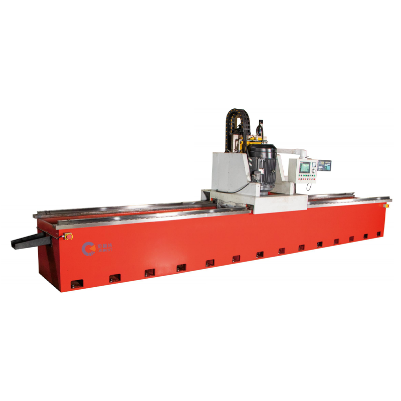
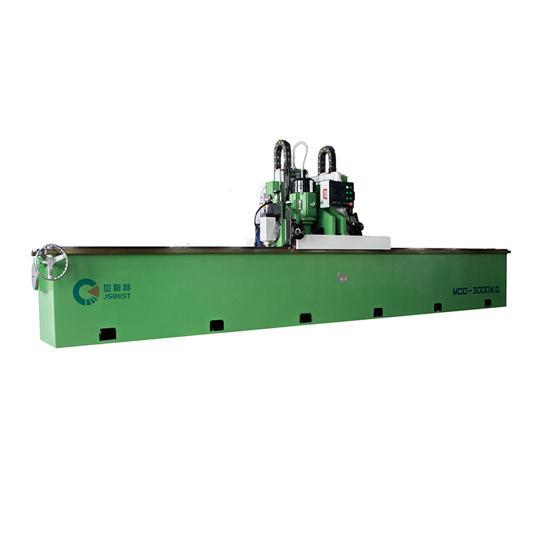
• The whole machine adopts a high-strength gantry-type welding structure, with a solid and compact o...
See Details -
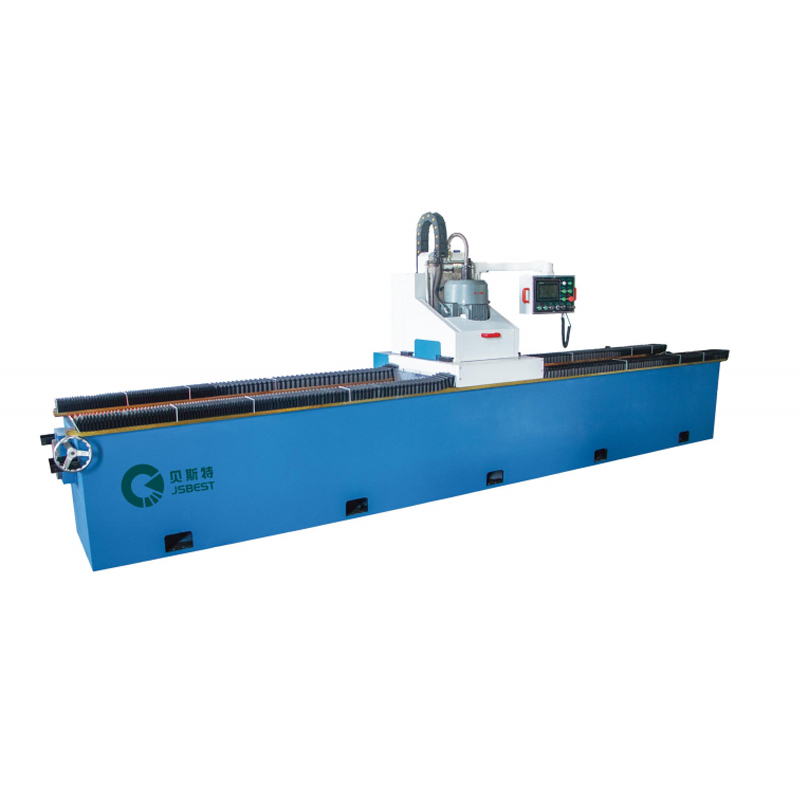
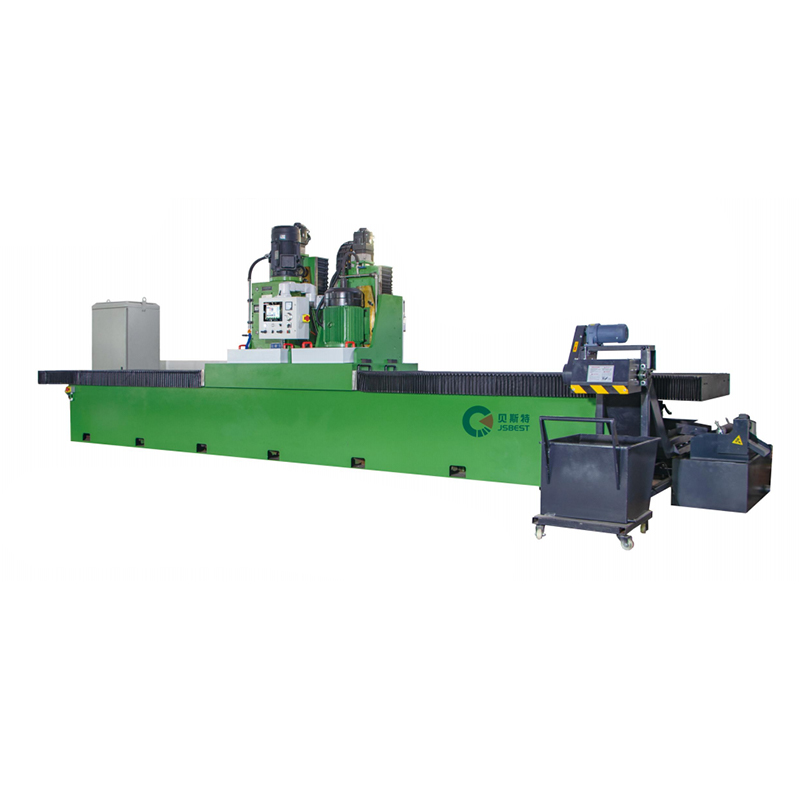
• The grinder adopts a gantry-type bed, high-quality steel plate welding, high-temperature tempering...
See Details -
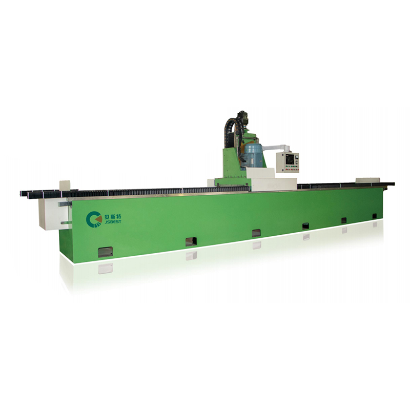
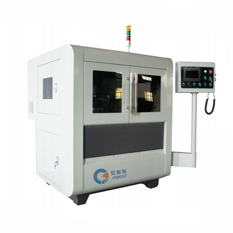
• A high-strength welded steel structure is adopted to eliminate the internal stress of the machine ...
See Details -
Double-Head Knife Grinding Machine is an efficient grinding equipment that combines rough grinding a...
See Details -
Heavy-Duty Surface Milling And Grinding Machine is an efficient processing equipment that integrates...
See Details -
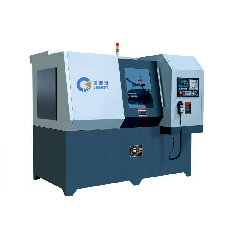
• This round knife grinder adopts a PLC program to control the automatic feeding part, which is easy...
See Details -
CNC Circular Knife Grinding Machine structural features:• High grinding accuracy, spindle and knife ...
See Details
- PRODUCT
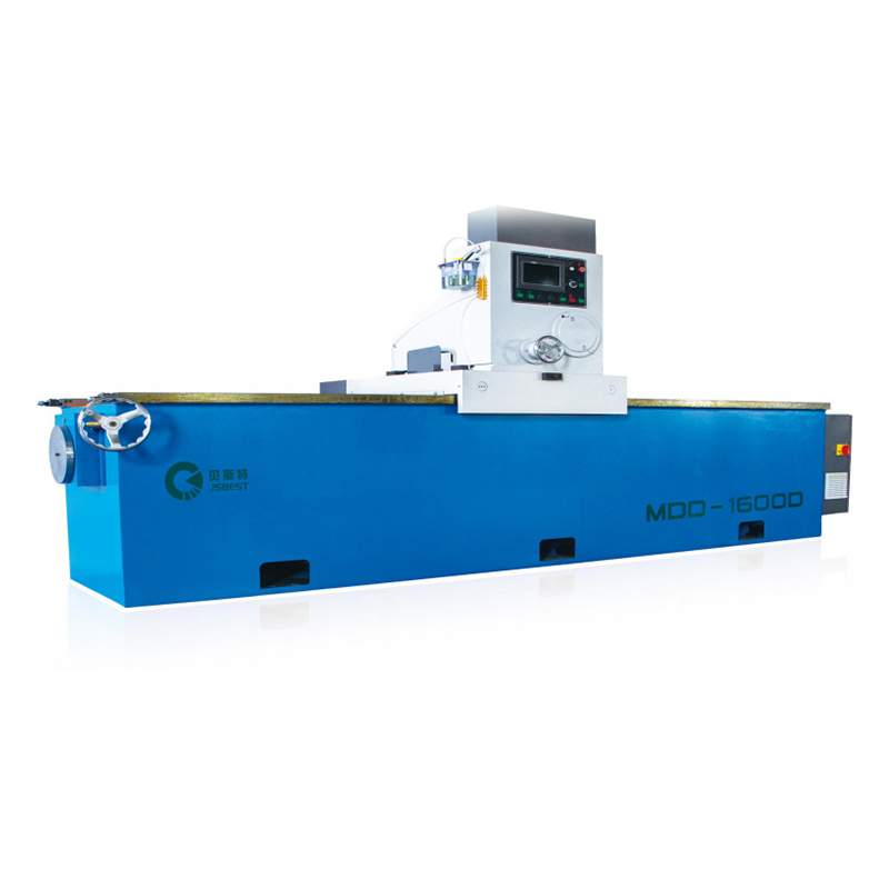
- MDD Series Straight Knife Grinding Machine
- MYD Series Circular Knife Grinding Machine
- MCD Series Rewinding Knife Grinding Machine
- QUICK LINKS
- About Us
- Manufacturing
- Industry Solutions
- Downloads
- Contact
- CONTACT US
-
-
 No.99, Huanghai South Road, Tangyang Town, Dongtai City, Jiangsu Province, China
 -
 0086-13818631306
 -
 +86-515-85652988
 -

-

