


 English
  中文简体
中文简体 • The CNC Knife Grinding Machine adopts PLC program control, which is easy to operate, fast, stable,...
See DetailsWhat is the working principle of a Straight Knife Grinding Machine?
Industry News-Content
- 1 Core Operating Principle: Linear Grinding Motion Along the Blade Axis
- 2 The Workbench and Fixture System: Foundation of Precision
- 3 Grinding Wheel Selection and Its Role in the Working Principle
- 4 Heat Generation and Thermal Control During Grinding
- 5 Edge Grinding and Flat Grinding: Two Distinct Operational Modes
- 6 CNC and Automatic Control in Modern Straight Knife Grinding Machines
- 7 The Complete Grinding Cycle: Step by Step
- 8 Key Performance Specifications and What They Mean in Practice
- 9 Applications Where the Straight Knife Grinding Principle Is Used
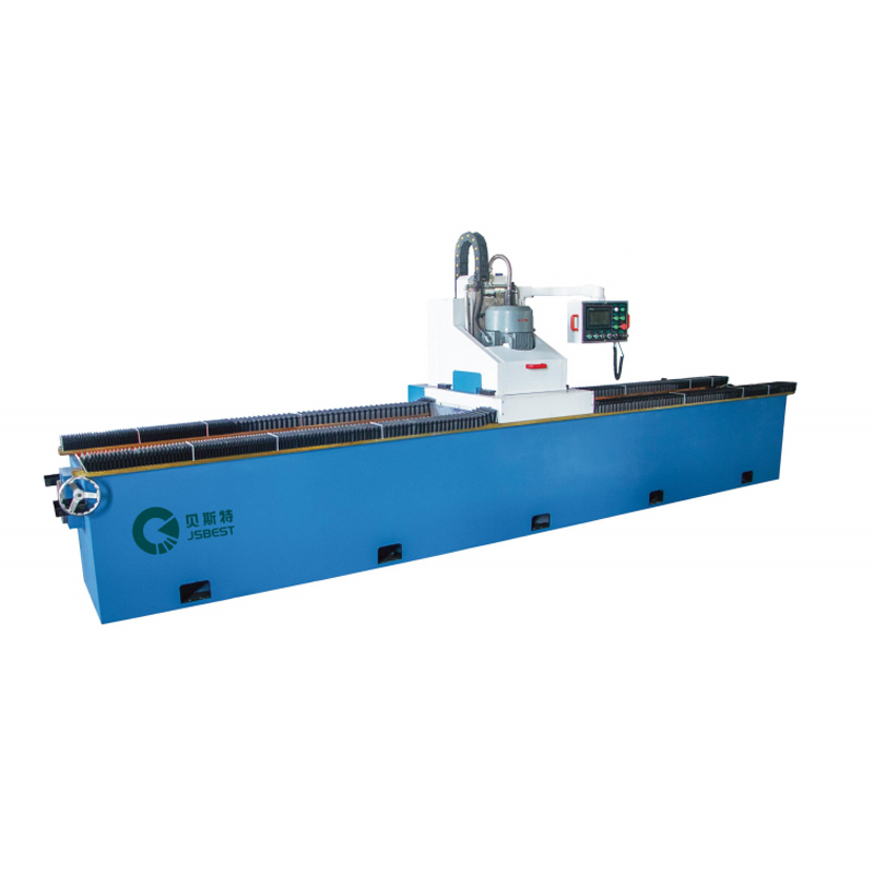
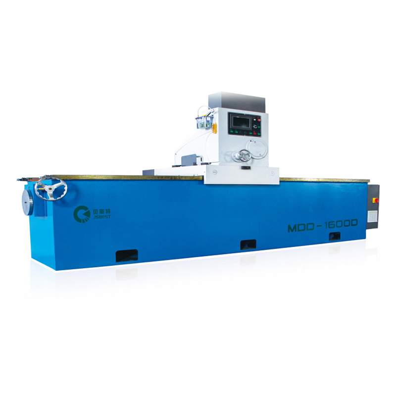
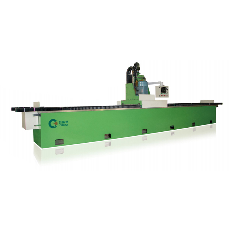
A straight knife grinding machine works by moving a rotating abrasive wheel in a precisely controlled path along the length of a stationary or slowly traversing straight blade, removing microscopic layers of material from the cutting edge or flat surface to restore sharpness, correct geometry, and eliminate surface defects. The blade is held rigidly in a dedicated workbench and fixture system that prevents any movement during grinding, while the grinding head travels along a linear axis parallel to the blade's length — ensuring uniform stock removal from tip to heel across the entire cutting edge in a single pass or a series of controlled passes.
Unlike general-purpose surface grinders, straight knife grinding machines are purpose-engineered for long, slender straight blades — from industrial cutting knives and paper slitter blades to woodworking planer blades and food processing cutters. Their specialized design addresses the unique challenges of maintaining edge straightness, controlling bevel angle consistency, and managing heat generation across blade lengths that can range from a few hundred millimeters to several meters. The sections below explain each element of the working principle in practical detail.
Core Operating Principle: Linear Grinding Motion Along the Blade Axis
The fundamental operating principle of a straight knife grinding machine is the coordination of two simultaneous motions: the rotational motion of the grinding wheel and the linear traversing motion of the grinding head or workpiece along the longitudinal blade axis. These two motions together produce the controlled abrasive cutting action that resharpens the blade edge and restores the flat ground surface.
Grinding Wheel Rotation
The grinding wheel — typically a vitrified or resin-bonded aluminum oxide or cubic boron nitride (CBN) wheel — rotates at high speed, commonly between 1,400 and 3,500 RPM depending on wheel diameter and the hardness of the blade material being ground. Each abrasive grain on the wheel surface acts as a miniature cutting tool, removing a tiny chip of blade steel with each contact. The cumulative effect of millions of abrasive grains contacting the blade surface per second produces a smooth, consistent stock removal rate that hand grinding or belt grinding cannot achieve with the same precision.
Linear Traversing Motion
While the grinding wheel rotates, either the wheel head or the workpiece table traverses linearly along the full length of the blade. This traversing motion is driven by a precision ball screw or rack-and-pinion mechanism and is controlled to deliver a consistent traverse speed — typically between 0.5 and 8 meters per minute depending on the depth of cut, blade hardness, and surface finish requirement. Slower traverse speeds produce finer surface finishes; faster traverse speeds increase productivity for coarser roughing operations.
The combination of wheel rotation speed and traverse speed determines the surface finish achieved on the ground edge. This relationship — the ratio of wheel peripheral speed to workpiece traverse speed — is a key process parameter that operators adjust based on the blade material, desired edge geometry, and finish specification.
Depth of Cut Control
In addition to the longitudinal traversing motion, the grinding head can be advanced toward the blade surface in the cross-feed direction to set the depth of cut per pass. Typical depth of cut per pass ranges from 0.005 mm for finishing passes to 0.05–0.1 mm for aggressive roughing on severely damaged or heavily dulled blades. Precision cross-feed mechanisms — often graduated in increments of 0.001 to 0.005 mm — allow the operator or CNC controller to apply exactly the right amount of material removal per pass without over-grinding, which would shorten blade service life unnecessarily.
The Workbench and Fixture System: Foundation of Precision
The accuracy of the grinding result depends entirely on the blade remaining absolutely stationary and correctly positioned relative to the grinding wheel throughout the entire grinding cycle. Any movement, vibration, or flex in the blade during grinding translates directly into edge waviness, inconsistent bevel angle, or surface chatter marks that defeat the purpose of precision grinding. The workbench and fixture system is therefore the most critical structural element of a straight knife grinding machine.
Rigid Workbench Construction
The machine bed and workbench are typically fabricated from heavy cast iron or welded steel with ribbed internal structures that provide high mass and rigidity. Cast iron is particularly favored for its superior vibration-damping characteristics — the graphite microstructure of gray cast iron absorbs vibration energy more effectively than welded steel, preventing grinding chatter from propagating into the blade surface. A well-designed machine bed maintains straightness to within 0.01 to 0.02 mm across its full working length, ensuring that the blade lies on a truly flat reference surface before clamping.
Clamping and Magnetic Fixturing
Straight knife grinding machines use one of two primary blade fixturing methods, or a combination of both:
- Electromagnetic chuck or magnetic rail: For ferromagnetic steel blades, a permanent magnet or electromagnetic rail running the full length of the machine table attracts and holds the blade flat against the reference surface with a holding force of typically 8 to 20 N/cm². This provides clean, rapid blade setup without mechanical clamping hardware that could interfere with the grinding wheel path. The electromagnetic system is deactivated after grinding to release the blade without the residual stress that mechanical unclamping can induce.
- Mechanical clamping system: For non-ferromagnetic blades (stainless steel grades with low magnetic permeability, or non-steel blade materials), mechanical clamps with precision-ground contact faces hold the blade at multiple points along its length. Clamp spacing is typically 200 to 400 mm to prevent blade deflection between support points during grinding.
- Adjustable angle fixture: A pivoting fixture block or sine bar assembly beneath the blade allows the bevel angle to be set precisely — typically adjustable from 10° to 45° — so that the grinding wheel contacts the blade at exactly the correct angle to reproduce or modify the original edge geometry.
Support for Long Blades
For blades exceeding 1 meter in length — common in industrial paper cutting, textile cutting, and food processing applications — the machine table incorporates additional intermediate support rails or adjustable steady rests that prevent the blade from deflecting under its own weight or the grinding force. Without these supports, long thin blades act as a beam under load and bow away from the reference surface at their unsupported midpoints, causing the ground edge to be non-straight despite the machine's own precision. Correct support setup for long blades is therefore as important as wheel specification and feed rate selection.
Grinding Wheel Selection and Its Role in the Working Principle
The grinding wheel is the cutting tool of the process, and its specification — abrasive type, grain size, bond type, hardness grade, and structure — determines whether the machine achieves the required edge quality on the specific blade material being ground. No single wheel specification is optimal for all blade materials and all stages of the grinding process, which is why experienced operators and machine manufacturers specify different wheels for roughing, semi-finishing, and finishing operations.
| Blade Material | Operation | Abrasive Type | Grain Size (Grit) | Bond Type |
|---|---|---|---|---|
| Carbon steel / tool steel | Roughing | White aluminum oxide (WA) | 36–46 | Vitrified |
| Carbon steel / tool steel | Finishing | White aluminum oxide (WA) | 80–120 | Vitrified |
| High-speed steel (HSS) | All operations | CBN (cubic boron nitride) | 80–150 | Resin or vitrified |
| Stainless steel | All operations | Pink aluminum oxide (PA) | 46–80 | Vitrified |
| Carbide-tipped blades | All operations | Diamond | 100–200 | Resin |
| Hardened tool steel | Finishing | CBN | 120–200 | Vitrified |
The wheel hardness grade — typically specified from G (soft) to P (hard) in the vitrified bond system — determines how readily abrasive grains break away from the wheel surface when they become dull. Softer wheel grades are used for hard blade materials to ensure that dull grains shed and expose fresh abrasive, preventing glazing of the wheel surface. Harder wheel grades are used for softer blade materials to maintain wheel form and resist excessive wear.
Heat Generation and Thermal Control During Grinding
Heat generation is one of the most critical challenges in straight knife grinding, and managing it correctly is central to the machine's working principle. The abrasive cutting process converts mechanical energy into heat at the point of contact between the wheel and the blade, and if this heat is not effectively removed, it accumulates in the blade's cutting edge — the thinnest and most thermally vulnerable zone of the entire blade body.
Excessive heat at the cutting edge causes several damaging effects:
- Thermal softening (over-tempering): When the edge temperature exceeds the tempering temperature of the hardened steel — typically 150°C to 200°C for most tool steels — the hardness of the cutting edge is permanently reduced, shortening its subsequent service life between sharpenings.
- Grinding burns: Localized overheating causes surface oxidation (visible as blue, brown, or yellow discoloration) and microstructural changes in the steel that create residual tensile stresses — a leading cause of edge chipping in service.
- Thermal distortion: Differential thermal expansion across the blade cross-section during grinding — hotter at the edge, cooler at the back — can cause the blade to bow, warp, or develop a curved profile that is extremely difficult to correct after cooling.
- Cracking: Severe thermal cycling during grinding can create surface micro-cracks that propagate under the mechanical stresses of subsequent cutting operations, causing premature blade failure.
Coolant Delivery System
Straight knife grinding machines address heat generation through a precision coolant delivery system that directs a continuous flow of grinding fluid directly into the contact zone between the wheel and the blade. Coolant flow rates of 5 to 20 liters per minute are typical, delivered through a nozzle positioned as close as possible to the wheel-blade contact arc to maximize thermal extraction before heat can conduct into the blade body.
The coolant serves three simultaneous functions: removing heat from the grinding zone, lubricating the contact interface to reduce friction heat generation, and flushing away swarf (ground metal particles and dislodged abrasive grains) that would otherwise re-enter the contact zone and cause surface scratching or secondary heating.
Coolant composition is matched to the blade material. Water-soluble synthetic coolants are standard for most steel blade grinding. Neat oil coolants are used for high-speed steel and carbide-tipped blades where maximum lubrication is required. For sensitive blades where water contact could cause rust staining, water-soluble coolants with rust inhibitor additives or oil-based fluids are specified.
Process Parameter Control for Thermal Management
Beyond coolant delivery, heat is managed through careful selection of grinding parameters. Reducing depth of cut and increasing traverse speed both reduce the heat input per unit area of blade surface, lowering peak temperatures at the contact zone. Spark-out passes — additional traverses at zero depth of cut after the final cutting pass — allow residual elastic deflection to be removed while producing minimal additional heat, improving dimensional accuracy and surface finish simultaneously.
Edge Grinding and Flat Grinding: Two Distinct Operational Modes
Straight knife grinding machines are designed to perform two fundamentally different grinding operations, each requiring a different wheel orientation, fixture setup, and process parameter selection.
Edge (Bevel) Grinding
Edge grinding resharpens the cutting bevel — the angled surface that forms the cutting edge of the blade. The blade is positioned in the angle fixture at the specified bevel angle, and the grinding wheel traverses along the blade length in contact with the bevel face. The wheel removes material uniformly from the bevel, advancing the cutting edge toward the blade back until a fresh, sharp cutting line is established across the full blade length.
For double-bevel blades (ground on both faces), the blade is flipped and re-clamped after grinding one face, and the process is repeated on the opposite face. The fixture angle is set symmetrically to maintain the original included angle of the cutting edge. Common bevel angles for industrial straight blades range from 15° to 35° per face, with narrower angles used for fine cutting applications and wider angles for blades subject to high impact forces.
Flat (Face) Grinding
Flat grinding restores the flat ground face of the blade — the opposite face from the primary bevel on single-bevel blades, or both flat ground faces on blades with ground flats behind the bevel. This operation addresses warping, surface pitting, or wear on the flat face that would otherwise prevent the blade from seating correctly in its holder or cause cutting inaccuracy. The blade lies flat on the magnetic table, and the grinding wheel — typically used in the peripheral or face grinding configuration — removes material uniformly across the flat face to restore flatness to within 0.005 to 0.02 mm across the blade width.
CNC and Automatic Control in Modern Straight Knife Grinding Machines
Modern straight knife grinding machines integrate CNC (Computer Numerical Control) systems that automate the grinding cycle, eliminating the variability introduced by manual operator control and enabling consistent, repeatable results across large production batches.
A CNC straight knife grinder can execute a complete multi-pass grinding program without operator intervention — automatically controlling traverse speed, depth of cut per pass, number of roughing and finishing passes, spark-out duration, and coolant delivery. The operator sets the program parameters once based on the blade specification and material, and the machine repeats the process identically for every blade in the batch, achieving edge-to-edge consistency that manual grinding cannot match.
Automatic Wheel Dressing
As the grinding wheel wears, its cutting surface becomes loaded with swarf or glazed with dull abrasive grains, reducing its cutting efficiency and degrading the surface finish it produces. CNC grinding machines incorporate an automatic wheel dressing system — a diamond dressing tool that the CNC controller brings into contact with the spinning wheel at programmed intervals to true and sharpen the wheel surface. Automatic dressing maintains consistent wheel geometry and cutting performance throughout the grinding shift without requiring the machine to be stopped for manual dressing — a significant productivity advantage over manually operated machines.
In-Process Measurement and Adaptive Control
Advanced CNC straight knife grinders incorporate in-process measurement systems — typically touch probes or air gauges — that measure the blade edge position or surface height at the start of the grinding cycle and after each pass. The CNC controller uses this data to automatically calculate the remaining material to be removed and adjust the number of passes and depth of cut accordingly, compensating for blade-to-blade dimensional variation. This adaptive control capability is particularly valuable when processing batches of blades from different production runs that may have slightly inconsistent starting dimensions.
The Complete Grinding Cycle: Step by Step
Understanding the working principle in its entirety requires seeing how all the individual elements described above combine into a complete grinding cycle. The following sequence describes a typical CNC straight knife grinding operation from blade loading to finished, sharpened blade removal.
- Blade inspection and preparation: The blade is visually inspected for chips, cracks, or severe damage that would affect the grinding approach. The blade back and flat face are cleaned of debris that could prevent accurate seating on the machine table.
- Blade loading and fixturing: The blade is placed on the workbench, aligned against the reference fence, and secured by activating the electromagnetic chuck or tightening the mechanical clamps. For angled bevel grinding, the fixture is set to the correct bevel angle using a precision angle gauge or digital protractor.
- Program selection and parameter input: The operator selects the appropriate grinding program in the CNC controller, or inputs blade-specific parameters including material, blade length, bevel angle, target edge geometry, roughing depth of cut, and number of finishing passes.
- Wheel dressing: The CNC controller automatically dresses the grinding wheel to ensure a fresh, correctly profiled cutting surface at the start of the grinding cycle. Dressing removes 0.01 to 0.05 mm of wheel material to expose sharp abrasive grains.
- Reference point setting: The grinding wheel is brought into light contact with the blade surface to establish the zero datum — the starting reference point from which all depth-of-cut increments are measured. Air gauge or touch probe systems perform this step automatically in fully automated machines.
- Roughing passes: The CNC controller executes the specified number of roughing passes at the programmed depth of cut per pass, traversing the wheel head along the full blade length at roughing traverse speed. Coolant is delivered continuously throughout. Each pass removes the bulk of the damaged or dull material from the edge.
- Semi-finishing passes: At reduced depth of cut (typically 0.01–0.02 mm per pass) and reduced traverse speed, semi-finishing passes refine the edge geometry established in roughing, removing the coarser surface texture left by the roughing wheel specification.
- Finishing passes: Final passes at minimal depth of cut (0.002–0.005 mm) and slow traverse speed produce the final edge sharpness and surface finish. For blades requiring mirror-finish edges, a very fine grit finishing wheel or superfinishing with honing film may follow.
- Spark-out passes: Additional traverses at zero depth of cut remove any remaining elastic deflection from the blade and grinding spindle, ensuring dimensional accuracy and a consistent final surface.
- Blade unloading and inspection: The coolant flow is stopped, the electromagnetic chuck is deactivated or mechanical clamps released, and the blade is carefully removed. Edge straightness, sharpness, bevel angle, and surface finish are verified before the blade is returned to service or passed to the next process step.
Key Performance Specifications and What They Mean in Practice
When evaluating a straight knife grinding machine, the following performance specifications directly reflect the practical capability of the working principle described above. Understanding what each specification means in operational terms allows buyers and production engineers to select the right machine for their application.
| Specification | Typical Range | Practical Significance |
|---|---|---|
| Maximum grinding length | 300 mm – 6,000 mm+ | Determines maximum blade length the machine can process in a single setup |
| Grinding wheel spindle speed | 1,400–3,500 RPM | Determines wheel peripheral speed; affects surface finish and material removal rate |
| Table traverse speed | 0.5–8 m/min | Balances productivity with surface finish quality; variable speed is essential |
| Cross-feed resolution | 0.001–0.005 mm/step | Minimum controllable depth of cut; finer resolution enables better finish and more controlled material removal |
| Workbench straightness | 0.01–0.02 mm/m | Directly determines the straightness of the ground blade edge; better tolerance = straighter edge |
| Bevel angle adjustment range | 0°–45° | Range of blade bevel angles the machine can grind; wider range increases application versatility |
| Electromagnetic chuck holding force | 8–20 N/cm² | Higher holding force prevents blade movement during aggressive roughing passes |
| Coolant flow rate | 5–20 L/min | Higher flow rates required for harder materials and higher material removal rates |
Applications Where the Straight Knife Grinding Principle Is Used
The working principle of the straight knife grinding machine is applied across a broad range of industries wherever long, straight blades are used in production cutting operations. The ability to restore a blade to its original geometric precision and cutting sharpness — rather than replacing it — delivers significant cost savings in any application where blade replacement costs are substantial or blade lead times are long.
- Paper and printing industry: Guillotine cutter blades, slitter blades, and sheeter knives of 500 mm to 2,000 mm length are resharpened on straight knife grinders to maintain cutting accuracy in paper and board production lines.
- Woodworking and timber: Planer blades, jointer knives, and veneer slicer blades — often in sets of 3 to 6 matched blades that must be ground to identical dimensions — are processed on straight knife grinders to maintain balanced rotation and consistent surface quality.
- Food processing: Industrial food slicing and portioning blades in meat, bread, cheese, and vegetable processing facilities are resharpened at regular intervals to maintain hygiene-compliant cutting edges that minimize product tearing and bacterial contamination risk.
- Textile and leather cutting: Long straight cutting blades used in automated fabric cutting machines and leather die-cutting presses are maintained on straight knife grinders to ensure clean, accurate cuts across wide material widths.
- Plastics and rubber: Slitting and shear blades used in plastic film, sheet, and rubber processing lines are resharpened to maintain the precise edge geometry required for clean separation without tearing or stretch deformation of the material.
- Metal fabrication: Shear blades and press brake tooling with long straight cutting edges are ground on straight knife grinders to restore edge geometry after wear or chipping in sheet metal cutting operations.
Across all these applications, the core working principle remains consistent: controlled abrasive material removal along a precision linear path, with rigid blade fixturing, thermal management through coolant, and systematic progression from roughing through finishing passes to restore the blade to its specified geometry and cutting performance. Mastery of this principle — in machine design, wheel selection, process parameter setting, and maintenance — determines whether a straight knife grinding operation delivers the blade quality and production efficiency that modern cutting operations demand.
Related products
-
-

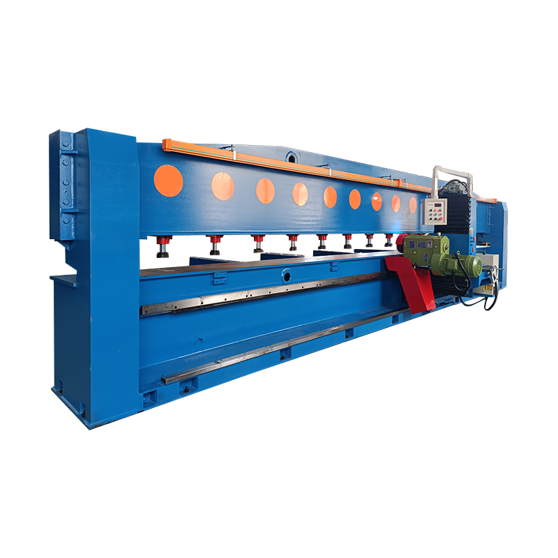
• The whole machine adopts a high-strength gantry-type welding structure, with a solid and compact o...
See Details -
• The grinder adopts a gantry-type bed, high-quality steel plate welding, high-temperature tempering...
See Details -
• A high-strength welded steel structure is adopted to eliminate the internal stress of the machine ...
See Details -
Double-Head Knife Grinding Machine is an efficient grinding equipment that combines rough grinding a...
See Details -
Heavy-Duty Surface Milling And Grinding Machine is an efficient processing equipment that integrates...
See Details -
• This round knife grinder adopts a PLC program to control the automatic feeding part, which is easy...
See Details -
CNC Circular Knife Grinding Machine structural features:• High grinding accuracy, spindle and knife ...
See Details
- PRODUCT
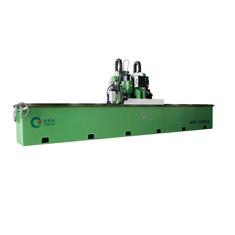
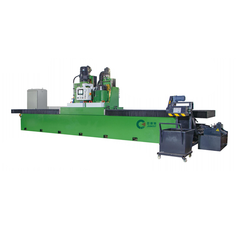
- MDD Series Straight Knife Grinding Machine
- MYD Series Circular Knife Grinding Machine
- MCD Series Rewinding Knife Grinding Machine
- QUICK LINKS
- About Us
- Manufacturing
- Industry Solutions
- Downloads
- Contact
- CONTACT US
-
-
 No.99, Huanghai South Road, Tangyang Town, Dongtai City, Jiangsu Province, China
 -
 0086-13818631306
 -
 +86-515-85652988
 -

-

